
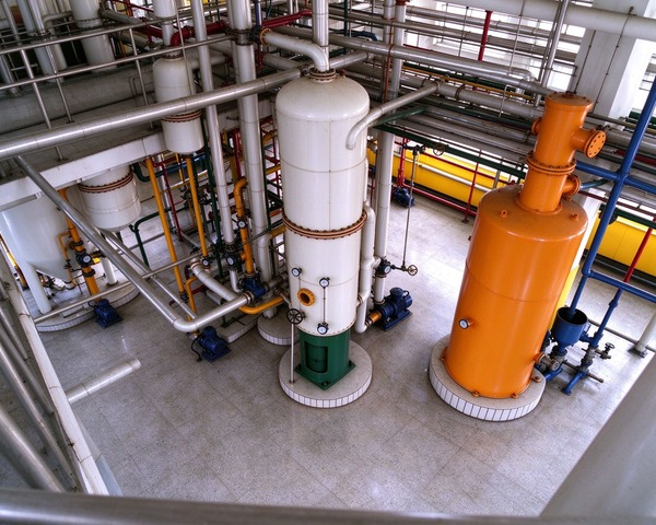
The Last Leg of Solvent Recovery Isn’t “Boiling Off Every Drop of Hexane” — It’s Finding an Operable Balance Between Residual Hexane, Steam and the Lower Explosion Limit
Solvent recovery in an extraction plant is often described as “boiling the hexane out of the miscella and condensing it back.” That’s not wrong, but it hides an engineering fact: the evaporators remove most of the hexane, but the last 2–5% of residual solvent cannot be economically removed by the evaporators alone. Concentrating the miscella from roughly 25–30% oil up to a high oil concentration is a job for evaporation. Pushing below that is a job for the stripper — using direct steam to lower the partial pressure of hexane so it escapes from the oil at a lower temperature.
Pushing residual hexane below 10 ppm is an industrially proven result. But the same process produces a vent gas stream carrying hexane, and its concentration must be held below 20% of the Lower Explosion Limit (LEL). Otherwise the recovery section stops being an “efficiency unit” and becomes a “safety risk unit.” And the heat integration between evaporators and stripper — using hot oil from the stripper to preheat the miscella entering the evaporators — determines how much steam the system consumes while still hitting the residual hexane target. A study of a large-scale soybean oil extraction plant gives a concrete reference point: integrating a heat exchanger network reduced direct steam from 620 kg/h to 270 kg/h and indirect heat duty from 6.44 MW to 5.05 MW.
The engineering essence of a solvent recovery system is finding a repeatable, operable balance point among residual hexane, steam consumption and the LEL safety threshold. KMEC has over two decades of experience configuring solvent extraction and recovery equipment. The sections below examine the division of labour between evaporation and stripping, the coupling between residual hexane and LEL, the energy lever of heat integration, and the hard constraints that explosion-proof area classification imposes on equipment selection.
1. Dividing the Work Between Evaporation and Stripping: Why the Last 2–5% Needs a Different Mechanism
1.1 The Evaporator’s Ceiling
Miscella leaving the extractor typically contains about 25–30% oil and 70–75% solvent. In the evaporation train, the first-stage evaporator removes most of the hexane and concentrates the miscella; the second-stage evaporator concentrates it further. But the evaporators themselves cannot push residual hexane low enough. The feed to the stripper is usually around 95–98% oil with 2–5% residual solvent — and that residual “cannot be removed by heating alone.”
Evaporator type affects both efficiency and oil quality at this stage. Rising-film evaporators (RFE) use rising vapour to drag a liquid film up the tube; the design is simple and suits continuous operation, working well with low-viscosity feed. Falling-film evaporators (FFE) rely on gravity to spread liquid as a thin film down the tube wall; heat transfer is more efficient and fouling is less likely, making them better suited to medium-to-high viscosity or heat-sensitive materials. For miscella — where overheating must be avoided to protect colour — the choice comes down to a trade-off between heat transfer efficiency and residence time.
1.2 The Stripper: Using Partial Pressure, Not Temperature, to “Coax Out” the Last Hexane
The stripper works on a different principle from the evaporator. It does not rely on higher temperature to evaporate hexane; it uses direct steam in counter-current contact with the oil to lower the gas-phase partial pressure of hexane, so hexane leaves the liquid at a relatively low temperature. Industrial sieve-tray strippers can hold crude oil residual hexane below 10 ppm at stripping temperatures of 95–105°C. That’s lower than conventional stripper operating temperatures, and the side benefit is better oil quality — fewer polymers and colour bodies form, and the downstream refining load drops.
There is a reference range for stripping steam consumption. The AOCS 2026 deodorization review gives a typical figure of 5–20 kg per tonne of oil — but note this is a deodorization reference, not a direct stripper figure. Actual stripper steam consumption depends on the residual hexane target, tray efficiency and operating pressure, and should be calculated by the supplier for the specific duty rather than borrowed from a generic number. KMEC’s oil stripper uses a two-stage steam design: first-stage steam enters the column body and contacts the downward-flowing miscella; oil forms a thin film on the trays, increasing gas–liquid contact area; second-stage steam is injected at the column bottom to remove further residual solvent; a portion of the partially treated oil returns to the column via a reflux line. The engineering goal is to push residual hexane reliably into the single-digit ppm range without relying on excessive temperature.
2. The Coupling Between Residual Hexane and LEL: Why “Stripping Clean” and “Venting Safe” Are the Same Problem
2.1 The Safety Threshold for Stripper Vent Gas
While removing hexane from the oil, the stripper produces a hexane-bearing vapour stream that goes to the condenser and then the mineral oil absorption system. The hexane concentration in that stream cannot rise without limit, because a hexane–air mixture enters the explosive range at a certain concentration. Hexane’s Lower Explosion Limit (LEL) is approximately 1.0–1.2% by volume.
The industry-standard safety control line is 20% of LEL. Desmet’s technical documentation states directly that the hexane content of vapour leaving the mineral oil system should be below 20% of LEL, corresponding to about 10 g/m³. This means the stripper and mineral oil absorption system must be designed to meet two targets simultaneously: push oil residual hexane below 10 ppm and hold gas-phase hexane below the LEL 20% safety line.
These two targets do not automatically align. Too little stripping steam and residual hexane won’t come down. Too much stripping steam and the gas phase is diluted — but steam consumption and condenser load go up, hurting economics. More critically, if the mineral oil absorber’s efficiency is insufficient, residual hexane in the vent can approach or exceed the LEL 20% line. At that point, even if oil residual hexane is compliant, the entire recovery section is in an unsafe state.
2.2 Mineral Oil Absorption: Pulling Hexane Back and Holding the Safety Line
The condenser only knocks down part of the hexane in the vent. The remaining non-condensable gas enters the mineral oil absorber. There, chilled food-grade mineral oil contacts the vent in counter-current flow, transferring hexane from gas to liquid. The hexane-rich mineral oil goes to a stripper, where steam strips the hexane; the mineral oil is cooled and returned to the absorber. A well-operated condensation plus mineral oil absorption system can exceed 95–98% overall recovery efficiency.
But the efficiency number is not the endpoint. The hexane concentration at the vent outlet is the direct safety-compliance indicator. By optimising the vacuum on the mineral oil stripper, some systems can push outlet hexane down to about 1 g/m³ — far below the 10 g/m³ LEL 20% line. When configuring the mineral oil absorption unit within a solvent recovery system, KMEC treats online LEL monitoring at the absorber outlet and stable mineral oil temperature control as design parameters equal in weight to recovery efficiency. “Recovery rate” alone is not the acceptance criterion.
3. Heat Integration: The Underrated Energy Lever Between Evaporator and Stripper
3.1 From 620 kg/h to 270 kg/h: A Quantified Reference for Heat Integration
Evaporation and stripping are both heat-intensive. If the two sections each consume steam independently, the recovery section’s energy demand will be significantly higher than necessary. Kong et al. (2019), studying a large-scale soybean oil extraction plant, provides a reference heat-integration path with quantified results. In the conventional process, direct steam injection is limited to the first-stage evaporator and the stripper, totalling 620 kg/h; indirect steam for the evaporators totals 6.44 MW. After integrating a heat exchanger network in the evaporation and stripping sections, direct steam drops from 620 kg/h to 270 kg/h and indirect heat duty from 6.44 MW to 5.05 MW. The desolventizing section’s energy demand falls from 8.15 MW to 2.12 MW. Overall gross energy savings are about 50%, wastewater load drops 56.5%, CO2 emissions drop 62.5%, and hexane emissions drop more than 90%.
The engineering meaning is concrete: heat integration is not “squeezing a few more percentage points of efficiency out of one machine” — it is reorganising the recovery section as a heat exchanger network, so heat that would otherwise be cooled is used to preheat material that would otherwise need external steam. Hot desolventized oil from the stripper bottom preheats the miscella entering the first-stage evaporator; vapour from the evaporators can be recovered and reused. Stacked together, these measures cut both direct steam and indirect heat duty — without sacrificing the residual hexane target or the LEL safety line, provided the network design does not interfere with the stripper’s own temperature control or the mineral oil system’s gas load.
3.2 The Boundary Conditions of Heat Integration
Heat integration is not unconditional. The network design must verify two constraints. First, the stripper’s temperature control cannot be “dragged down” by the preheat duty. If too much heat is drawn off on the evaporator side, the oil temperature at the stripper bottom may fall below the window needed for the residual hexane target (on the order of 95–105°C) — and heat integration then sacrifices the residual hexane spec. Second, the mineral oil system’s gas load cannot exceed its design range because of evaporator vapour recovery. Heat integration changes where heat goes, not how much hexane is present; if vapour recovery shifts the gas flow or hexane concentration entering the absorber, the LEL 20% safety margin must be re-verified.
When configuring a solvent recovery system, KMEC treats heat integration as a constrained optimisation problem: first lock the stripper’s residual hexane target and the absorber’s LEL outlet concentration, then design the heat exchanger network within those boundaries — not pursue “maximum heat recovery” first and patch the safety margin afterwards.
4. Explosion-Proof Areas: The Hard Constraints of Zone 1/Zone 2 on Equipment Selection
4.1 What the Area Classification Actually Means
The solvent recovery section sits in a flammable gas atmosphere. Under the NFPA 36 framework, the extraction process boundary is Class I, Division 1 (or Zone 1); the restricted area (beyond 4.5 m up to 15 m) is Division 2 (or Zone 2); the controlled area (15–30 m) is Division 2, applied only above a certain height above grade. Under the GB 50058 framework, the solvent recovery unit area and extraction workshop are classified as Zone 1 or Zone 2, with a typical explosion-proof rating requirement of Ex d IIA T4 Gb.
The constraints these classifications impose on equipment selection are specific: motors, instruments and lighting near the stripper and evaporators must use explosion-proof types matched to the area; the vent outlet of the mineral oil absorption system requires a flame arrestor to prevent external flame from propagating back into the system; online LEL monitoring should cover the absorber outlet, condenser non-condensable vent, and other key points, interlocked with nitrogen blanketing or emergency relief. Explosion-proof rating is not an “optional extra” — it is a precondition for the equipment to be legally installed and operated.
4.2 The Decision Sequence for Equipment Configuration
For a new or revamped solvent recovery section, the configuration sequence should start from safety constraints, not from “maximum recovery rate”:
Step one: define the vent flow and hexane concentration corresponding to the LEL 20% line. Size the mineral oil absorber and absorbent circulation rate from these, ensuring the outlet concentration stays below the safety threshold at maximum load.
Step two: set the stripper’s residual hexane target (typically below 10 ppm). Verify that the stripping steam rate required for that target matches the mineral oil system’s gas load. KMEC’s oil stripper configuration determines tray count, steam distribution and operating temperature window from the target residual hexane and oil type — not from a “universal” stripper specification.
Step three: design the evaporator–stripper heat exchanger network within the residual hexane and LEL constraints. Determine the first-stage evaporator’s heating area and flow arrangement so that the steam savings from heat integration (on the order of 620→270 kg/h) do not interfere with the stripper’s temperature window or the mineral oil system’s gas load.
Step four: procure LEL monitoring, flame arrestors and explosion-proof electricals as items of equal rank to the process equipment — not as installation-stage add-ons. For clients running both oil press machines and extraction lines, the prepress cake residual oil level propagates into the extraction section’s solvent load and the recovery system’s gas flow. The recovery section’s LEL safety design therefore needs to be coordinated with the upstream pressing configuration.
5. FAQ
Q1: What roles do the evaporator and stripper play in solvent recovery?
The evaporators remove most of the hexane from the miscella, concentrating it from about 25–30% oil to a high oil content. But the last 2–5% of residual solvent cannot be economically removed by evaporation alone. The stripper uses direct steam to lower the hexane partial pressure and pushes residual hexane below 10 ppm at a relatively low 95–105°C.
Q2: How low can stripper residual hexane go?
Industrial sieve-tray strippers at 95–105°C hold crude oil residual hexane below 10 ppm. The lower stripping temperature also reduces polymer and colour body formation, improving crude oil quality.
Q3: What is the safety threshold for the mineral oil absorption system?
The hexane content of vapour leaving the mineral oil system should be below 20% of LEL, about 10 g/m³. A well-operated condensation plus mineral oil absorption system can exceed 95–98% recovery efficiency, but outlet hexane concentration is the direct safety-compliance indicator — recovery rate alone is not the acceptance criterion.
Q4: How much steam can evaporator–stripper heat integration save?
A study of a large-scale soybean oil extraction plant found that integrating a heat exchanger network in the evaporation and stripping sections cut direct steam from 620 kg/h to 270 kg/h and indirect heat duty from 6.44 MW to 5.05 MW, with overall gross energy savings of about 50%. Heat integration must be verified against the stripper’s temperature window and the mineral oil system’s gas load — it cannot come at the cost of the residual hexane target or the safety margin.
Q5: What is a typical stripping steam consumption?
The AOCS 2026 deodorization review gives a typical steam figure of 5–20 kg per tonne of oil, but this is a deodorization reference, not a direct stripper figure. Actual stripper steam consumption depends on the residual hexane target, tray efficiency and operating pressure, and should be calculated for the specific duty.
Q6: What explosion-proof requirements apply to electrical equipment in the solvent recovery section?
Under NFPA 36 and GB 50058, the solvent recovery unit area is typically classified as Zone 1 or Zone 2, with a typical explosion-proof rating of Ex d IIA T4 Gb. The mineral oil absorber vent requires a flame arrestor, and online LEL monitoring should be interlocked with nitrogen blanketing or emergency relief. Explosion-proof rating is a precondition for legal installation and operation, not an optional configuration.
References
- Kong, W., Baeyens, J., De Winter, K., Urrutia, A.R., Degrève, J. & Zhang, H., “An energy-friendly alternative in the large-scale production of soybean oil,” 2019, FAO AGRIS — heat exchanger network integration reduces direct steam from 620 kg/h to 270 kg/h and indirect heat duty from 6.44 MW to 5.05 MW; overall gross energy saving ~50%; hexane emissions reduced >90%.
- Desmet, Mineral Oil High Vacuum Stripper — hexane content of vapours from the mineral oil system should be below 20% of LEL, about 10 g/m³; patented system can reduce outlet hexane to about 1 g/m³.
- Desmet, Sieve Tray Oil Stripper — counter-current stripping at 95–105°C; residual hexane consistently below 10 ppm; low temperature preserves crude oil quality.
- AOCS 2026, “Deodorizing — how to decide the best conditions to use,” May 2026 — steam required typically 5–20 kg per tonne of oil; pressure 2–4 mbar; lower pressure reduces steam mass but raises vacuum energy.
- NFPA 36, Standard for Solvent Extraction Plants — Class I, Division 1 (or Zone 1) at extraction process boundary; restricted area beyond 4.5 m to 15 m classified Division 2 (or Zone 2); controlled area 15–30 m Division 2 (above ground level).
- GB 50058, 爆炸危险环境电力装置设计规范 — solvent recovery area and extraction workshop classified as Zone 1 or Zone 2; typical explosion-proof classification Ex d IIA T4 Gb.
- KMEC, Oil Stripper — Solvent Removal Equipment — two-stage steam design; residual solvent reduced to single-digit ppm range; reflux design returns partially treated oil to the column.
- KMEC, Solvent Evaporator — miscella in first-stage evaporator heated by high-temperature oil from the oil stripper; waste steam recycled to first-stage evaporator.
For solvent recovery system configuration, oil stripper or solvent evaporator selection, LEL safety-line verification, or heat-integration assessments for extraction plants, contact the KMEC engineering team.